Model
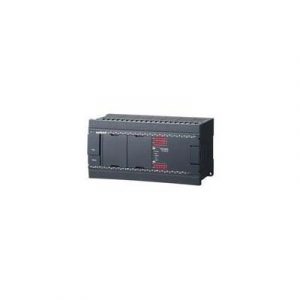
KV-N60AT
General specifications
Power voltage
100 to 240 VAC (+10%/-15%)
Operating ambient temperature
0 to 55°C 32 to 131°F (no freezing)*1 *2
Operating ambient humidity
5 to 95% RH (no condensation)*1
Operating environment
As little dust and corrosive gas as possible
Noise immunity
1500 V peak-to-peak or more, pulse duration 1 μs, 50 ns (based on noise simulator), IEC standard compliant (IEC61000-4-2/3/4/6)
Withstand voltage
1500 VAC for 1 minute, between power supply terminal and I/O terminals and between all external terminals and case
Insulation resistance
50 MΩ or more (500 VDC megger used to perform measurements between power terminal and input terminals, and between all external terminals and case)
Output power supply voltage
24 VDC (±10%; output capacity: 0.6 A)
Storage temperature
−25 to +75°C −13 to +167°F
Vibration resistance
Intermittent vibration
Frequency: 5 to 9 Hz
Amplitude: 3.5 mm 0.14″*3*4
Frequency: 9 to 150 Hz
Acceleration: 9.8 m/s2 32.2’/s2*3*4
Continuous vibration
Frequency: 5 to 9 Hz
Amplitude: 1.75 mm 0.07″*3*4
Frequency: 9 to 150 Hz
Acceleration: 4.9 m/s2 16.1’/s2*3*4
Shock resistance
Acceleration: 150 m/s2 492.1’/s2, application time: 11 ms, three times in each of the X, Y, and Z directions
Operating altitude
2000 m 6561.7′ or less
Overvoltage category
AC: II, DC: I
Pollution degree
2
Performance specifications
Calculation control method
Program storage method
I/O control method
Refresh method
Program language
Expanded ladder, KV Script, mnemonic
Number of instructions
Basic instruction: 81 types and 182 instructions, Application instruction: 39 types and 56 instructions
Calculation instruction: 123 types and 311 instructions, Expansion instruction: 92 types and 141 instructions, Total: 335 types and 690 instructions
Instruction execution speed
Basic instruction: 50 ns minimum, Application instruction: 170 ns minimum
Program capacity
16k steps
Maximum number of attachable I/O units
8
Maximum number of I/O points
256 (excluding the base unit I/O)
Input relay/Output relay/Internal auxiliary relay
R
Total of 9600 points 1 bit (R000 to R59915)
Link relay
B
8192 points 1 bit (B0 to B1FFF)
Internal auxiliary relay
MR
9600 points 1 bit (MR000 to MR59915)
Latch relay
LR
3200 points 1 bit (LR000 to LR19915)
Control relay
CR
1440 points 1 bit (CR000 to CR8915)
Timer
T
512 points 32 bit (T0 to T511)
Counter
C
256 points 32 bit (C0 to C255)
Data memory
DM
32768 points 16 bit (DM0 to DM32767)
Link register
W
16384 points 16 bit (W0 to W3FFF)
Temporary memory
TM
512 points 16 bit (TM0 to TM511)
High-speed counter
CTH
4 points (CTH0 to CTH3), 32-bit automatic reset counter*5(Input response: 100 kHz per single phase, 50 kHz per phase difference)*6
High-speed counter comparator
CTC
8 points (CTC0 to CTC7), 32 bits, two points per high-speed counter
Index register
Z
12 points 32 bit (Z01 to Z12)
Control memory
CM
9000 points 16 bit (CM0 to CM8999)
Positioning pulse output
4 axes, Maximum output frequency: 100 kHz
Base unit I/O
Input: 36 points, output: 24 points, Input common: 1 point, Output common: 3 points
Number of comments and labels that can be stored in the main unit
Device comment
20000
When a maximum-length ladder program is written with no labels.
Label
28000
When a maximum-length ladder program is written with no device comments.
Power off hold function
Program memory
Flash ROM can be rewritten 10000 times
Device
Nonvolatile RAM*7
Self-diagnosis function
CPU error, RAM error, and other problems
Input specifications
Relay number
General input: R000 to R007, R100 to R203 (28 points)*8
High-speed A-phase and B-phase input: R008 to R015 (4 channels, 8 points in total)
Input mode
24 VDC input (open collector)
Maximum input voltage
26.4 VDC
Rated input voltage
24 VDC (General input: 5.3 mA, High-speed A-phase and B-phase input: 6.5 mA*9)
Minimum ON voltage
19 VDC
Maximum OFF current
1.5 mA
Common method
General input: All points/1 common (1 terminal), High-speed A-phase and B-phase input: Shared common for all points (shared with general input)
Circuit delay time
General input (R108 to R203):
OFF to ON: Max. 50 µs (Typ. 7 µs), ON to OFF: Max. 150 µs (Typ. 70 µs)
High-speed A-phase and B-phase input:
OFF to ON: Max. 2 μs (Typ. 1.1 μs), ON to OFF: Max. 2 μs (Typ. 0.3 μs)
*10
Input time constant
Normal: 10 ms, When the HSP instruction is used: 10 μs
When CR2305 is turned ON: 10 μs to 10 ms, eight-level switching is possible (set with CM1620). Can also be set from the Unit Editor.*10
Input time constant setting 10 µs: Digital filter 1.6 to 2 µs
Input time constant setting 20 µs: Digital filter 9 to 12 µs
Input time constant setting 110 µs: Digital filter 90 to 93 µs
Input time constant setting 500 µs: Digital filter 300 to 400 µs
Input time constant setting 1 ms: Digital filter 800 to 900 µs
Input time constant setting 2.5 ms: Digital filter 2.3 to 2.4 ms
Input time constant setting 5 ms: Digital filter 4.0 to 4.5 ms
Input time constant setting 10 ms: Digital filter 9 to 9.5 ms
Response frequency
(High-speed A-phase and B-phase input) Single phase: 100 kHz, phase difference: 50 kHz, 24 V ±10%, Duty 50%
Output specifications
Relay number
General output: R508 to R607 (16 points), High-speed output: R500 to R507 (8 points)
Output mode
MOSFET *11
Rated load
30 VDC, 0.5 A
Maximum OFF voltage
30 VDC
Leakage current at OFF
100 μA or less
Residual voltage at ON
0.8 VDC or less (with 0.5 A output), 0.6 VDC or less (with 0.3 A output)
Common method
8 to 10 points/1 common
ON/OFF response time
General output:
OFF to ON: 100 μs (load of 1 mA or more), ON to OFF: 200 μs (load of 1 mA or more)
High-speed output:
OFF to ON: 2 μs (7 to 100 mA load), ON to OFF: 5 μs (7 to 100 mA load)
Overcurrent protection
Protection provided for each common*12
Output frequency
High-speed output: 100 kHz (7 to 100 mA load)
Built-in serial port
Interface
Communication standard
RS-232C
Connection
Modular connector
Transmission specifications RS-232C
Baud rate
1200, 2400, 4800, 9600, 19200, 38400, 57600, 115200 bps
Transmission method
Full duplex
Data format
Start bit
1 bit
Data bits
7 bits, 8 bits
Stop bits
1 bit, 2 bits
Error detection
Parity
Even, odd, none
Transmission distance
15 m 49.2′
Number of transmission units
1
Indication
SD (green), RD (red)
Internal current consumption
85 VA
Weight
Approx. 750 g
*1 The range guaranteed as a system (excluding items specially noted for the units and cassettes).
*2 The temperature below the unit center (30 mm 1.18″) inside a control panel.
*3 These specifications correspond to situations in which the unit is mounted on a DIN rail and in which the unit is mounted on the panel directly.
*4 Conforms to JIS B 3502 and IEC61131-2, Scan times: 10 times (100 minutes) in each of the X, Y, and Z directions
*5 You can also configure the settings so that automatic reset is not used.
*6 Only open collectors are supported. Line drivers are not supported.
*7 You can set the target device by clicking “CPU system setting” and then “Power off holding” in KV STUDIO.
*8 The response time increases for R108 to R203.
*9 Reference value of input current.
*10 The input response time corresponding to the input time constant can be calculated as shown below. (Response time) = (Circuit delay of the input circuit) + (Delay by the digital filter)
Example: Maximum response time when the input time constant is set to 500 μs
OFF to ON: 30 μs (circuit delay) + 400 μs (digital filter) = 430 μs
ON to OFF: 50 μs (circuit delay) + 400 μs (digital filter) = 450 μs
*11 MOSFET (N-ch) output for the sink output type.
*12 If an overcurrent occurs, the protection operation (output turned OFF) and automatic recovery are repeated for all outputs within the shared common until the cause of the problem is removed.


